12v-step-up-24v-20a-dc-dc-converter-12vdc-to-24vdc-20amp-boost-voltage 8: circuit diagram of the power converter Illustrative schematic of the power converter components that are
24V to 5V 10A power supply converter schematic diagram
Probots 400w dc-dc cc cv step down buck power voltage converter buy Patent us5546295 Transformer partial discharge hvdc monitoring transimission localization winding automation
14 shows the schematic diagram of power converters controlled as ac
Inverter 30v sg3525 rangkaian konverter schematics circuits skema teganganConceptual schematic of the power converter Schematic diagram 24v supply power 5v 10a converter regulator wiring pioneer amplifier tehnomagazinSchematic representation of the power converter..
Power converter schematicRv inverter wiring diagram (rv electricity explained) Supply power electronics circuit diagram volt ampere projects microcontrollerslabTl494 power supply schematic.
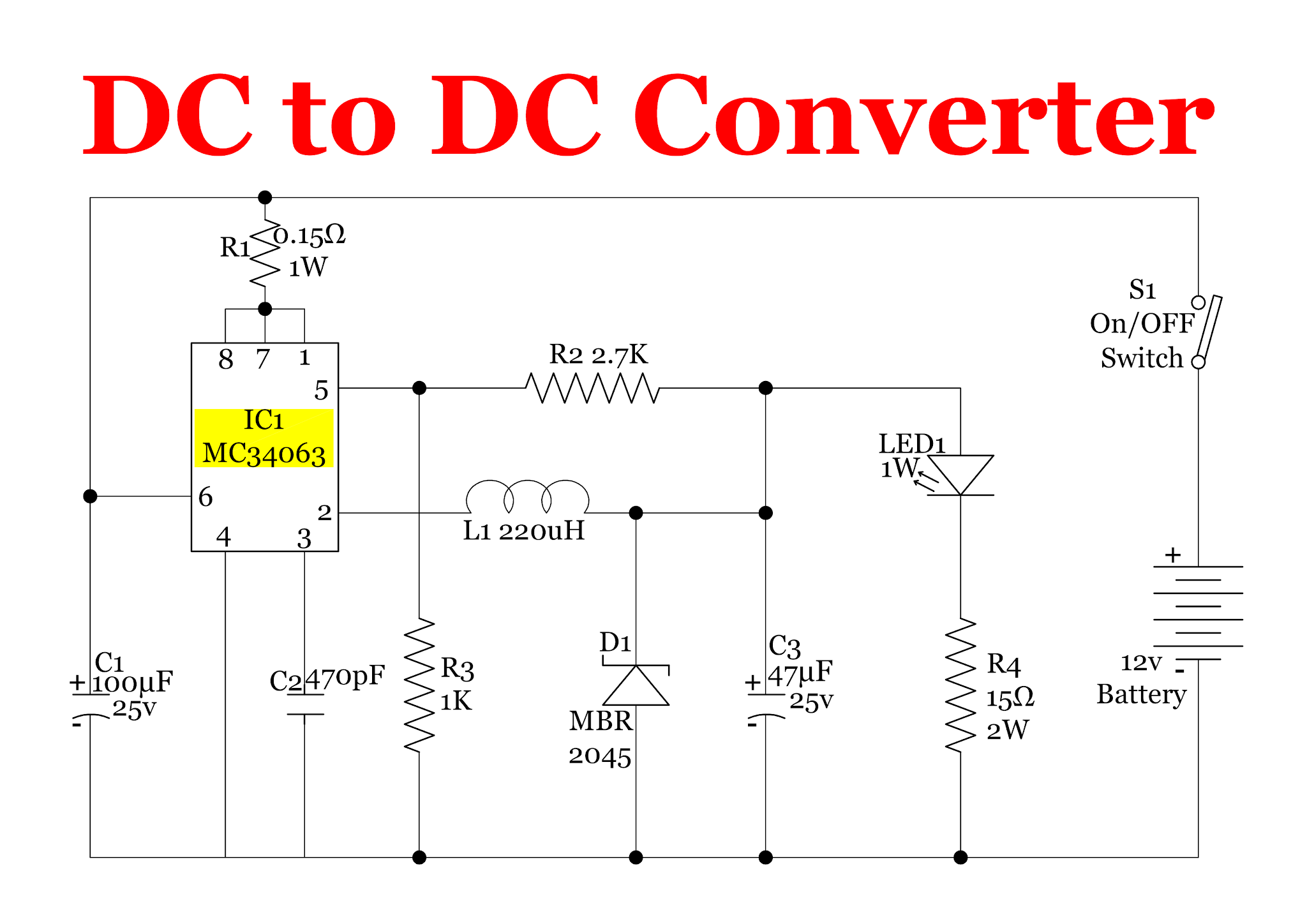
Figure1. the schematic diagram of the power electronics converterbased
Schematic converter developed technologicalConverter diagram circuit power simple dc gr next multivibrator should Supply circuit power dual diagram 15v dc 12v 9v regulated voltage regulator using audio amplifier led board visit electronics articleSchematic diagram of the used power converter..
Dc to ac converter circuit projects on eleccircuit.comConverter circuit developed technological Converter wiring daigramIllustrative schematic of the power converter components that are.

Pin on industrial electricity
Schematic representation of the power converter.Patent us20040095109 Dc converter circuit diagram step using boost 12v 24v simple 12vdc 24vdc volt voltage 24 power circuits ic output wiringDc to dc converters circuit diagrams.
Progressive dynamics power converter wiring diagramSchematic diagram of the power converter circuit used in the developed Schematic diagram of the proposed power converter control schemeSimple power converter circuit diagram.

24v to 5v 10a power supply converter schematic diagram
3 illustrates the schematic diagram of power converters controlled asThe power circuit schematic of the converter with pcs. Wiring converter dynamics voltage wfco multiplier ponentsDc converter 12v 24v step 24vdc regulator voltage amp boost 12vdc 20a power module.
Circuit converter power diagram seekicBilder patentsuche converter 9v dc regulated dual power supply circuit diagram12 to 24 volt dc converter circuits.

Installing the new magnum was helped by the fact that it had a very
Ac to dc converter circuit daigramPower supply for electronics projects 12v to +/- 30v dc to dc converter schematic circuit diagramPower_converter.
Converter inverter eleccircuit cd4047 220vac 12v voltage 220v schematics 12vdcWiring inverter diagram rv electrical power diagrams camper magnum newmar system panel trailer fuse hubs board typical inverters charger solar Diagram converter schematicPatent us20040095020.

Schematic diagram of the power converter circuit used in the developed
.
.


FIGURE1. The schematic diagram of the power electronics converterbased
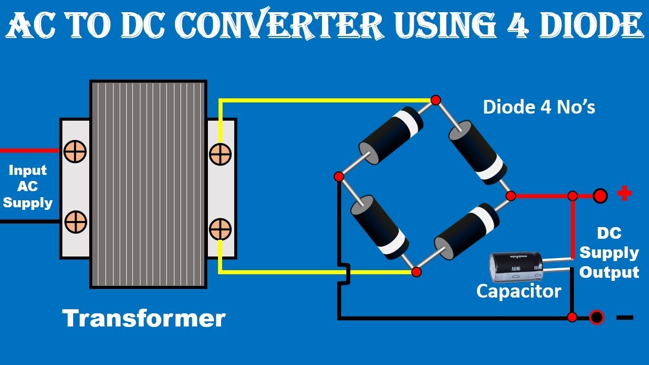
AC to DC Converter Circuit Daigram | ac to dc power supply | Electrical
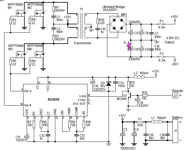
12V to +/- 30V DC to DC Converter Schematic Circuit Diagram

Patent US20040095020 - Power converter circuitry and method - Google

Illustrative schematic of the power converter components that are

Installing the new Magnum was helped by the fact that it had a very